Carbon Steel Physical Properties
Corrosion Resistance:
Early fasteners relied on applying a thin layer of .00015 inch to .0005 inch of Electro-deposited zinc plating with .0003 being the norm. This was done in order to prolong the fastener life and to improve the appearance. A considerable number of years ago, Atlas pioneered the introduction and use of the Mechanical-Zinc plating process, which eliminates Hydrogen-embrittlement in the manufacturing process. One more advantage is the increased thickness range of deposited zinc ranging from .0003 inch to .001 inch, with .0005 being the norm.
Prior to plating, all carbon steel fasteners are case-hardened to create a hard surface for drilling and tapping while maintaining a softer core for ductility. Parts can also have added corrosion protection, by optionally coating fasteners with long life coating, either alone or in conjunction with a conventional paint finish that substantially increases the life of the fastener.
Metal Composition:
C .20-.25
Mn .80-1.10
P .040
S .050
| Specific Gravity | 7.75 |
|---|---|
| Density | |
| lb/in³ | 0.280 |
| kg/m³ | 7,750 |
| Mean Specific Heat | |
| Btu/ib °F (32/212°F) | 0.11 |
| J/kg K (0/100°C) | 460 |
| Electrical Resistivity (RT) | |
| ohm-cir mil/ft | 343 |
| microhm-mm | 570 |
| Mean Coefficient of Thermal Expansion | |
| 10-6/°F(32/1200°F) | 6.5 |
| 10-6k(0/649°C) | 11.7 |
| Thermal Conductivity | |
| Btu in/fth²h °F(212V) | 173 |
| Wm K(100°C) | 25.0 |
| Modulus of Elasticity (E) | |
| ksi | 29.0 x 10³ |
| MPa | 200 x 103 |
410 SS Physical Properties
Corrosion Resistance:
Stainless Type 410, in both annealed and heat-treated conditions, provides good corrosion resistance to mild atmospheres. It resists corrosion in many light industrial and domestic environments as well as potable and mine waters.
The alloy has acceptable resistance to sulfide stress cracking at Rockwell C 22 maximum hardness per NACE MR-01-75, "Sulfide-Stress-Cracking-Resistant Metallic Materials for Oil Field Equipment." Refer to the current document for details on acceptable conditions.
For optimum corrosion resistance, surfaces must be free of scale and foreign particles and finished parts should be passivated.
Metal Composition:
C .15
Mn 1.00
P .040
S .030
Si 1.00
Cr 11.5 - 13.5
| Specific Gravity | 7.75 |
|---|---|
| Density | |
| lb/in³ | 0.280 |
| kg/m³ | 7,750 |
| Mean Specific Heat | |
| Btu/ib °F (32/212°F) | 0.11 |
| J/kg K (0/100°C) | 460 |
| Electrical Resistivity (RT) | |
| ohm-cir mil/ft | 343 |
| microhm-mm | 570 |
| Mean Coefficient of Thermal Expansion | |
| 10-6/°F(32/1200°F) | 6.5 |
| 10-6k(0/649°C) | 11.7 |
| Thermal Conductivity | |
| Btu in/fth²h °F(212V) | 173 |
| Wm K(100°C) | 25.0 |
| Modulus of Elasticity (E) | |
| ksi | 29.0 x 10³ |
| MPa | 200 x 103 |
304 SS Physical Properties
Corrosion Resistance:
Annealed Project 70 stainless Type 304 is resistant to atmospheric corrosion, foodstuffs, sterilizing solutions, many organic chemicals and dyestuffs, and a wide variety of inorganic chemicals.
Intergranular corrosion may be a problem if the material is heated between 800°F (427°C) and 1650°F and (899°C) or cooled slowly through that range.
For optimum corrosion resistance, surfaces must be free of scale and foreign particles and finished parts should be passivated.
Metal Composition:
C .08
Mn 2.00
P .045
S .030
Si 1.00
Cr 18.0 - 20.0
Ni 8.0 - 10.5
| Specific Gravity | 7.90 |
|---|---|
| Density | |
| lb/in³ | 0.285 |
| kg/m³ | 7,900 |
| Mean Specific Heat | |
| Btu/ib °F (32/212°F) | 0.12 |
| J/kg K (0/100°C) | 500 |
| Electrical Resistivity (RT) | |
| ohm-cir mil/ft | 433 |
| microhm-mm | 720 |
| Mean Coefficient of Thermal Expansion | |
| 10-6/°F(32/1200°F) | 10.4 |
| 10-6k(0/649°C) | 18.7 |
| Thermal Conductivity | |
| Btu in/fth²h °F(212V) | 113 |
| Wm K(100°C) | 16.3 |
| Modulus of Elasticity (E) | |
| ksi | 28.0 x 10³ |
| MPa | 193 x 103 |
| CARBON &410 STAINLESS STEEL | |||
|---|---|---|---|
| Fastener Strength | (TENSILE VALUES ARE FOR HEX WASHER HEAD & HEX HEAD FASTENERS) | ||
| FASTENER DIAMETER | MINIMUM TENSILE (LBS.) | MINIMUM TORQUE (IN LBS.) | MINIMUM SHEAR (LBS.) |
| #6-20 | 1,125 | 25 | 750 |
| #8-18 | 1,575 | 42 | 1,000 |
| #9-16 | 2,350 | 65 | 1,500 |
| #10-16 | 2,100 | 61 | 1,400 |
| #10-24 | 2,350 | 65 | 1,500 |
| #12-14 | 2,800 | 92 | 2,000 |
| #12-24 | 3,250 | 100 | 2,100 |
| 1/4-20 | 4,275 | 168 | 2,700 |
| #17-14 | 5,200 | 175 | 3,125 |
| #18-9 | 4,550 | 170 | 2,575 |
| 304 STAINLESS STEEL | |||
|---|---|---|---|
| Fastener Strength | (TENSILE VALUES ARE FOR HEX WASHER HEAD & HEX HEAD FASTENERS) | ||
| FASTENER DIAMETER | MINIMUM TENSILE (LBS.) | MINIMUM TORQUE (IN LBS.) | MINIMUM SHEAR (LBS.) |
| #14-10 | 2,925 | 125 | 1,925 |
| 1/4-14 | 3,600 | 150 | 2,600 |
| #17-14 | 5,200 | 170 | 3,125 |
| DECIMAL (INCH) EQUIVALENT | DECIMAL (INCH) EQUIVALENT | ||
|---|---|---|---|
| THREAD DIAMETER | DECIMAL EQUIVALENT | GAUGE | THICKNESS (IN.) |
| #6 | .140 | 26 | .018 |
| #7 | .150 | 24 | .024 |
| #8 | .160 | 22 | .030 |
| #9 | .180 | 20 | .036 |
| #10 | .190 | 18 | .048 |
| #11 | .200 | 16 | .060 |
| #12 | .210 | 14 | .075 |
| #13 | .230 | 12 | .105 |
| 1/4" | .240 | 10 | .134 |
| #14 | .250 | 8 | .164 |
| #17 | .285 | 4 | .224 |
| #18 | .304 | 1/4 | .250 |
| 11/32" | .344 | ||
| RECOMMENDED DRIVING SPEED | |
|---|---|
| DRILLING FASTENERS | ELECTRIC SCREW GUN WITH DEPTH SENSING NOSE PIECE |
| #6 THRU #10 | 2,500 RPM MAX |
| #12 THRU #18 TCP 1, 2, 3 | 2,000 RPM MAX |
| #12 THRU 1/4 TCP 4, 5 | 1,800 RPM MAX |
| SELF-TAPPING FASTENERS | |
| CARBON & 410 STAINLESS | 2,000 RPM MAX |
| .300 STAINLESS | 800 RPM MAX |
| FASTENER SIZE | WASHER O.D |
|---|---|
| #8 THRU #10 | 1/2" |
| #12 THRU 1/4" | 15MM |
| #18 | 15MM |
Metal to Metal Fastening to Determine Drilling Tip Length
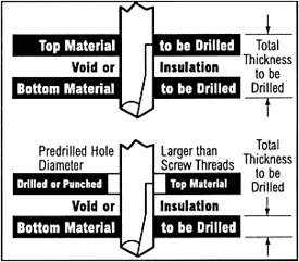
The length of the tip required on a drilling fastener is determined by adding up the thickness of the top material, any insulation or void between the top material and bottom material, and the thickness of the bottom material. If a hole larger than the screw thread has been pre-drilled or punched into the top material, only the thickness of the bottom material need be considered. The threaded portion of the shank must be long enough to extend into and through the bottom material drilled.

Socket Information
Recommend 5/16" retaining ring socket, which allows good fastener head engagement into socket and keeps fastener perpendicular to the work surface. If magnetic sockets are used, be sure to set magnet depth prior to use.

Washer Seating Recommendation


Fastener Selection
to minimize Galvanic Action (Corrosion) Between Fastener and Base Metal
| FASTENER METAL | ||||||
|---|---|---|---|---|---|---|
| BASE METAL | ZINC & GALVANIZED STEEL | ALUMINUM & ALUMINUM ALLOYS | STEEL & CAST IRON | BRASS, COPPER, BRONZE, MONEL | MARTENSITIC STAINLESS 410 | AUSTENITIC STAINLESS 302/304, 303, 305 |
| ZINC & GALANIZED STEEL | A | B | B | C | C | C |
| ALUMINUM & ALUMINUM ALLOYS | A | A | B | C | NR | B |
| STEEL & CAST IRON | AD | A | A | C | C | B |
| TERNE (LEAD-TIN) PLATED SHEET | ADE | AE | AE | C | C | B |
| BRASS, COPPER, BRONZE, MONEL | ADE | AE | AE | A | A | B |
| FERRITIC STAINLESS STEEL (430) | ADE | AE | AE | A | A | A |
| AUSTENITIC STAINLESS STEEL (302/304) | ADE | AE | AE | AE | A | A |
KEY
A - corrosion of the base metal is not increased by the fastener
B - corrosion of the base metal is marginally increased by the fastener
C - corrosion of the base metal may be markedly increased by the fastener
D - plating on the fastener is rapidly consumed, leaving the bare fastener metal
E - corrosion of the fastener is increased by the base metal
NR - not recommended
Note: Surface treatment and environment can change activity.
Fastener Selection Chart and Suggested Drill Sizes
| FASTENER SELECTION CHART AND SUGGESTED DRILL SIZES | |||||||
|---|---|---|---|---|---|---|---|
| #14 TYPE A 1/4" TYPE B & BP | 1/4" TYPE B & BP | 1/4" TYPE AB | #17 TYPE AB | ||||
| STEEL GAUGE | HOLE SIZE | STEEL GAUGE | HOLE SIZE | STEEL GAUGE | HOLE SIZE | STEEL GAUGE | HOLE SIZE |
| #26 | 1/8" | 3/16"-3/8" | #2 BIT | #26 | 1/8" | #26 | 3/16" |
| #24 | 5/32" | 3/8" & OVER | #1 BIT | #24 | 5/32" | #24 | 3/16" |
| #22 | 5/32" | #22 | 5/32" | #22 | 3/16" | ||
| #20 | 5/32" | #20 | 5/32" | #20 | 1/4" | ||
| #18 | 3/16" | #18 | 3/16" | #18 | 1/4" | ||
| #16 | 3/16" | #16 | 3/16" | #16 | 1/4" | ||
| #14 | #7 BIT | #14 | #7 BIT | #14 | 1/4" | ||
| #12 | #7 BIT | #14 | 1/4" | ||||
| 1/8" | #2 BIT | #10 | 16/64" | ||||
| #10 | #2 BIT | ||||||
All test results and recommendations are based on laboratory tests. Hole sizes for material thicker than 14 gauge are based on 50,000 psi hot rolled structural steel. Specific job site conditions should be taken into consideration when specifying the proper fastener. Because applications vary, we assume no liability for use of this information.
